Cype-Tower, When analyzing structures, there are several different methods that are used. The method most often used in analysis is the finite element method. The finite element method was also used in the elaboration of the problem herein, and it is related to displacement in plate structures. Numerical models will be approximated by finite triangular elements in the CYPE program and by finite square elements in the TOWER 3D Model Builder program. In the end, a comparison will be made of the results and of the influence of the type and density of the finite element mesh as well as the quality of the concrete on the result of the analysis. Key words: analysis, triangular mesh, square mesh, deflection, concrete, CYPE, TOWER https://www.adriabim.com/cype/
Matej Lozančić
University of Mostar, Faculty of Civil Engineering, Architecture, and Geodesy, M.Eng.C.E.
matej.lozancic@fgag.sum.ba
Marko Mandić
markom@e-disti.com
Vlaho Akmadžić
University of Mostar, Faculty of Civil Engineering, Architecture and Geodesy, prof. Ph.D C.E.
vlaho.akmadzic@fgag.sum.ba
1. INTRODUCTION
Discretization of the area is a basic step when using the finite element method. A discretized structure is one that is divided into a mesh of finite elements. Considering the behavior of the structure in reality there are two types of errors, model errors and discretization errors. Model errors can be approximated by a higher-quality model of the structure that will better and more realistically describe the actual behavior of the structure. Discretization errors can be reduced by a higher-quality mesh of finite elements or by increasing the degrees of freedom (polynomials of a higher degree) of the finite elements for describing the displacement field[1], [2].
For each element, the solution of the given differential equation is assumed in the form of interpolation functions that relate the dependent variables with their values at the nodes. A system of algebraic equations the unknowns of which are the values at the nodes is derived, after which a global system of equations is formed for the entire discretized model, in which the unknowns are the values at the nodes of all elements of the discretized areas. There are one-dimensional, two-dimensional and three-dimensional finite elements. The simplest finite element is a one-dimensional element, i.e. a beam with two nodes and with linear
interpolation [3].
- All other elements are more complex.
The finite element method consists of five steps:
preprocessing – the problem is divided into finite elements (discretization of
calculation models) - element formulation – developing the equation for elements (formulating the local
element stiffness matrix) - assembly – obtaining equations for the entire system from equations for individual
elements (forming a global system of equations) - solving equations
- post-processing – determining the results, obtaining visualization [4]
2. NUMERICAL MODEL ACCORDING TO KIRCHHOFF’S THEORY
A planar beam loaded perpendicular to its central plane is observed. Such a beam is called a plate. It is assumed that the plate thickness is constant and equal to d. The thickness of the plate is of a smaller order of magnitude compared to the remaining two dimensions of the plate, length and width. The basic assumptions are that there are no relative deformations in the central plane, that the points of the vertical to the central plane are located on one straight line perpendicular to the deformed central plane even after bending of the plane, that is, that Bernoulli’s hypothesis of flat cross sections applies and that stresses perpendicular to
the plate can be ignored. Then, it can be assumed for all points of the central plane that their deflection occurs only perpendicular to the central plane of the plate.
The coordinate system is set so that the central plane coincides with the xy plane. The points of the central plane have coordinates (x, y, 0), and after deformation they have coordinates (x, y, w). An arbitrary point at a distance z from the central plane, (x, y, z), after deformation, has coordinates (x + uz, y + vz, z + wz), which means that it gets displacements in the direction of all three coordinate axes. Based on the assumption of plate thickness as a dimension of a lower order of magnitude than the other two dimensions, it follows [1], [4], [5]:
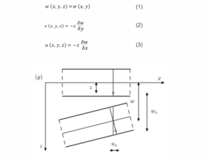
Figure 1. View of part of the plate before and after deformation [4]
3. OBSERVED TESTS
In the following examples, the cases of different density of the finite element mesh in the CYPE software package will be analyzed, as well as the influence of different quality of concrete on the vertical displacement. It is important to point out that the CYPE software package uses a triangular mesh of finite elements. This makes it different from the TOWER software package, which uses a rectangular mesh of finite elements. The obtained data of the two software packages will be compared in the continuation of the paper.
3.1 The first example – a freely supported plate
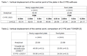
The dimensions of the square plate taken from paper [5] are 10.0 x 10.0 x 0.1 m. The plate material has characteristics of Young’s modulus of elasticity of 27 GPa and Poisson’s ratio of 0.2. The density of the mesh of square finite elements varies from 4×4 to 32×32. On the other hand, the density of the triangular mesh of finite elements is given by the maximum length of a triangle side. The force acting in the direction of gravity is given at the central point of the plate, and has an intensity of 100.0 kN. Figure 2 shows the plate with minimum discretization in the CYPE software package. Figure 3 shows the vertical displacement for the simplest finite element mesh, and by analyzing Table 1, it is observed that it is the largest for this mesh in the CYPE software package. Figure 4 shows the densest distribution of finite elements in the CYPE software package and at the same time the smallest (most precise) value of vertical displacement.
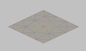
Figure 2. Plate with minimum discretization of the mesh – CYPE
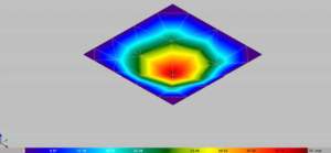
Figure 3. Vertical displacement of a freely supported plate – CYPE (maximum length of the triangle side 4 m)
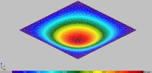
Figure 4. Vertical displacement of a freely supported plate – CYPE (maximum length of the triangle side 0.5 m)
3.2 Second example – a fixed plate
During the analysis of the fixed plate, the same geometric and material characteristics and density of the finite element mesh are assumed. The obtained results are shown in Table 1. Figure 5 shows an example of the distribution of triangular finite elements and the deflection value for a triangular mesh with a triangle side length of 2m.
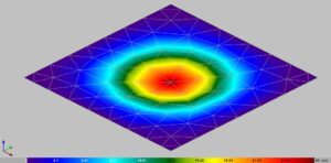
Figure 5. Vertical displacement of the fixed plate – CYPE (maximum length of the triangle side 2 m)
Results of the vertical displacement of the central point at different densities of the finite element mesh are shown below. In the case of triangular mesh (CYPE), it is the maximum given length of the side of the triangular element when generating the mesh.
The presented values listed in Table 2, related to the results obtained in the TOWER 3D Model Builder 7 software package and the CYPE software package, were compared for approximately the same number of finite elements to which the surface was discretized, which is 1652 square finite elements in TOWER and 1651 triangular finite elements in CYPE. The graphic presentation of displacements and moments from the TOWER software package is not shown in this paper due to space limitations, but it is clearly presented in the literature [8] through square meshes of finite elements 4×4, 8×8, 16×16 and 32×32.
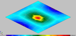
Figure 6. Bending moment of the fixed plate, Mx – CYPE
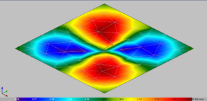
Figure 7. Bending moment of the fixed plate, Mxy – CYPE
The influence of concrete quality on the displacement of the central point of the plate is shown in Table 3 in the CYPE program, in which the set maximum side length is 2 m.
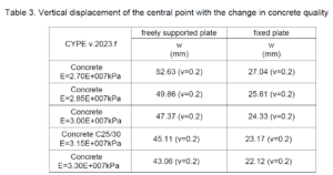
Table 3. Vertical displacement of the central point with the change in concrete quality
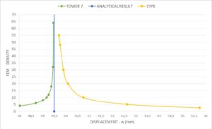
Figure 8. Accuracy of deflection results with respect to finite element mesh density on a
freely supported plate
4. CONCLUSION
The paper analyzed numerical models using two software packages that rely on different forms of finite element mesh. The results of the triangular finite element mesh from the CYPE software package were compared with the square finite element mesh from the TOWER software package. The goal was to present the work and the possibility of data processing in the CYPE v.2023.f software package through graphical and numerical indicators.
Analyzing the obtained results, it is evident that the deviations from the analytical solution are small and that for the densest distribution in the CYPE software package, they are almost identical to the analytical results. It is important to note that changes in concrete quality have an effect only on the displacement segment, while this is not the case with the bending moment. The ultimate goal is the best possible approximation of the real state of the structure, and it is achieved by the necessary density of the finite element mesh.
Upon examination of the vertical displacements and finite element mesh, it is evident that in the CYPE software package, the mesh with the triangle side of 4 m gives greater deflections (55.74 mm) than the mesh with the triangle side of 0.25 m (49.96 mm), which indicates that the mesh with dense FEs gives a more accurate result with respect to the analytical calculation. The 4×4 mesh (square sides 2.5 m) in TOWER gives smaller displacements (48.03 mm) than the 32×32 mesh (square sides 0.3125 m) which gives larger displacements (49.45 mm), but again with the same analogy that a denser mesh gives a more accurate result (Figure 8.).
REFERENCES
1. Meštrović, M.: Metoda konačnih elemenata, Sveučilište u Zagrebu, Građevinski fakultet,
Zagreb, 2020
2. Mihanović, A., Trogrlić, B., Akmadžić, V.: Građevna statika II., Fakultet građevinarstva,
arhitekture i geodezije u Splitu, Split, Hrvatska, 2014, ISBN 978-953-6116-57-7
3. Sorić, J.: Uvod u numeričke metode u strojarstvu, Sveučilište u Zagrebu, Fakultet
strojarstva i brodogradnje, Zagreb, 2009
4. Fish, J., Belytschko, T.: A First Course in Finite Elements, Wiley, USA, 2007
5. Ramljak, D., Akmadžić, V.: Influence of the mesh density and concrete quality on the
results accuracy in thin plates, XVIII Anniversary International Scientific Conference by
Construction and Architecture VSU’2018, Volume 1, pp. 341-350, Sofia, 2018
6. Akmadžić, V.: Model velikih pomaka u analizi plošnih i linijskih konstrukcija (Model of large
displacements in the analysis of planar and linear structures), Doctoral thesis, Faculty of Civil
Engineering, University of Mostar, Mostar, 2008
7. Lozančić M., Akmadžić, V.: Construction of toll station building on the highway, e-Zbornik:
Electronic Journal of the Faculty of Civil Engineering University of Mostar, Vol. 10, No. 20, 92
p., (https://doi.org/10.47960/2232-9080.2020.20.10.92), Mostar, 2020
8. Raspudić, V., Akmadžić, V., Lozančić, M.: Comparison of the convergence of results on
the example of a thin plate, XXII International scientific conference VSU’2022, Volume II, pp.
67-75, Sofia, 2022
9. Timoshenko, S. P., Gere, J. M. Theory of elastic stability, McGraw-Hill, 541 p., London,
1986
10. Raspudić, V., Akmadžić, V., Lozančić, M.: Selected examples of the patch tests, XXII
International scientific conference VSU’2022, Volume II, pp. 77-83, Sofia, 2022
11. Raspudić V.: Nauka o čvrstoći, pregled teorije i tablice, Sveučilište u Mostaru, 220 p.,
Mostar, 2016, ISBN 978-9958-16-062-2


