Overview
“CYPE Architecture” has been developed with the aim of surpassing the modelling powers of IFC Builder, with a considerable improvement in this through a new 3D work environment without geometric restrictions and greater modelling capacities that contemplate the conceptual design phase of the project.
“CYPE Architecture”, like its predecessor IFC Builder, is a free application.
In the creation of the CYPE Architecture program, two fundamental phases have been taken into account when developing a project digitally: the architectural design process and the 3D/BIM modelling process. The aim has been to adopt tools from both traditional modelling (surfaces, edges, intersections, extrusions, curves, etc) and from the new BIM modelling (walls, slabs, roofs, columns, etc), which combined allow the user to easily move from the conceptual to the architectural.
CYPE Architecture includes new architectural elements such as: curtain walls, louvres, roof tiles, screed to falls, beams, curved ramps and swimming pools, and offers more detail in elements like doors, windows, skylights and guardrails.
In addition, “CYPE Architecture” is an umbrella program for other modules developed by CYPE such as: Open BIM Vertical Connections, Open BIM Suspended Ceilings, Open BIM Office Furniture, Open BIM Residential Furniture and Open BIM Water Equipment.
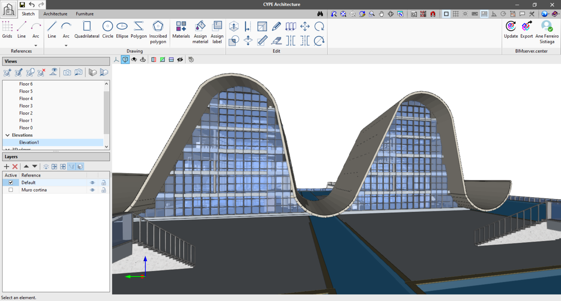
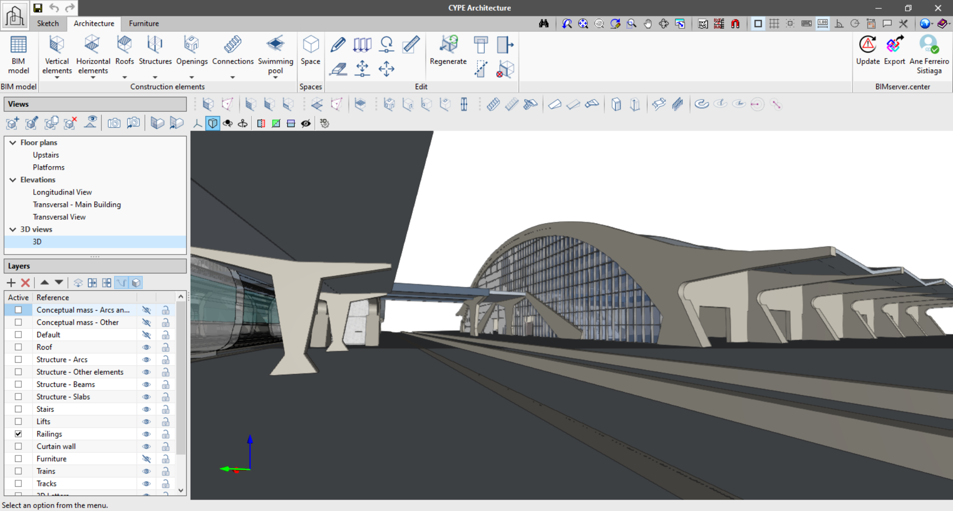
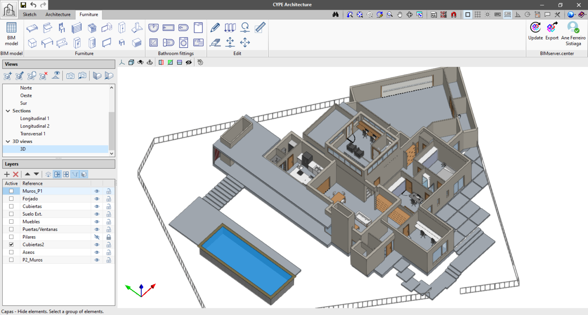
Sketch-Architecture and Furniture
The CYPE Architecture program has been developed under the “sketch-architecture” duality where first the user can “conceive the building” using the Sketch tab, to then later give it an architectural entity through the BIM modelling of its elements, in the Architecture tab. Finally, CYPE Architecture offers the possibility of furnishing the building using the Furniture tab.
- Sketch
The sketch tab includes features and tools typical of traditional modelling programs such as: lines, arcs, quadrilaterals, circles, polygons, extrusion, intersection, offset or scaling. The aim is that from this tab users can freely design the project concept, both from the volumetric conception of the shape and uses, as well as the drawing of the floor layout diagrams. - Architecture
The architecture tab includes features and tools typical of BIM modelling programs such as: walls, slabs, roofs, guardrails, louvres, stairs, ramps, etc. From this tab users can either reuse the sketches and diagrams to generate an architectural model in BIM by adding detail to the initial sketch, or go directly to the BIM modelling of the building using a CAD template. - Furniture
An approximate distribution of the furniture is fundamental for the design of the building in order to allow the end users to understand it. To finish the model furniture can be included through the furniture tab. This tab includes the Open BIM Residential Furniture, Open BIM Office Furniture and Open BIM Water Equipment modules.
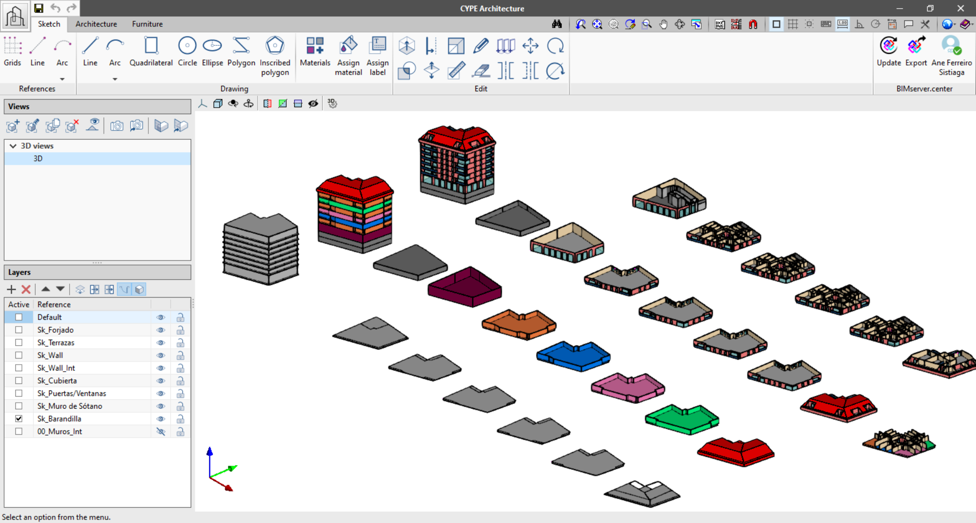
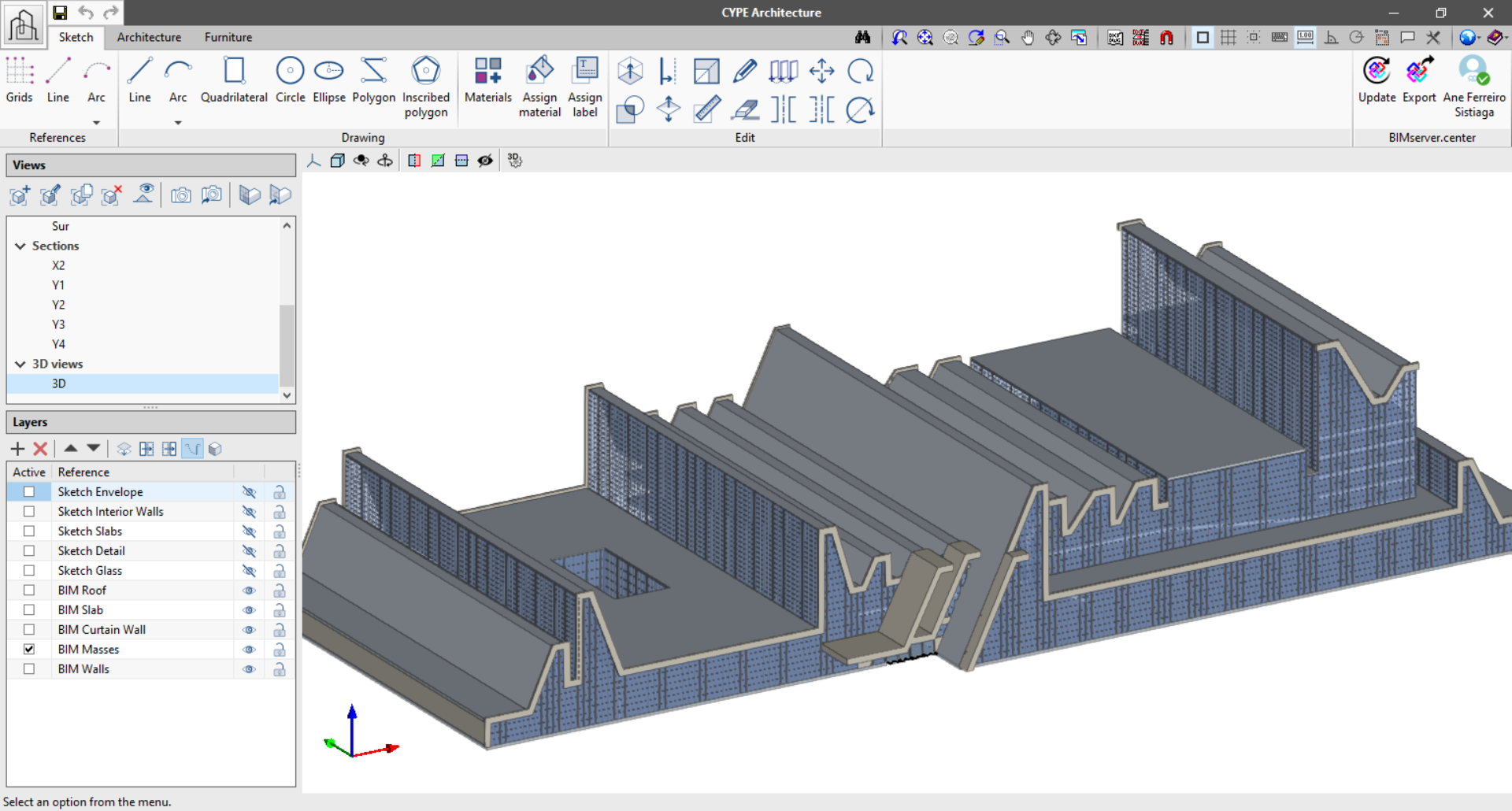
3D interface
CYPE already has previous experience in the development of 3D interfaces with programs such as CYPE3D, the Open BIM Systems (manufacturer systems) and the StruBIM programs. With the “CYPE Architecture” tool, our software is fully introduced into the 3D world, adapting to the new possibilities and innovations that the development and programming of Architecture, Engineering and Construction software offers these days.
The new 3D interface is managed from the right side of the program by using the views and layers.
- Views
From here users can manage and create views to work with their project. Create floor plans, elevation, section, ceiling plan, free or 3D views. During the modelling process users can travel through the views for greater ease when introducing elements.
- Layers
The different model elements, both those from the “Sketch” tab and those from the “Architecture” tab, can be classified using a system of layers that can be edited by the user. The aim is to allow users to create their own classification which facilitates their 3D modelling of the building.
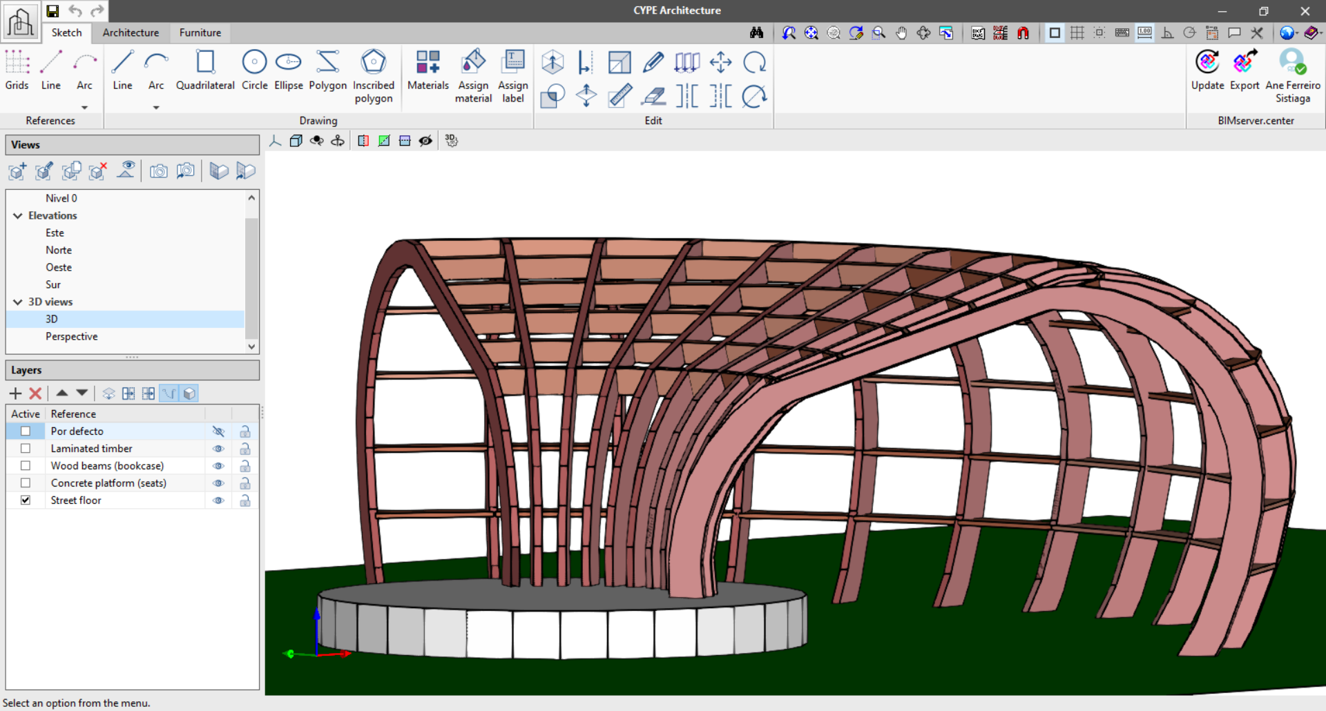
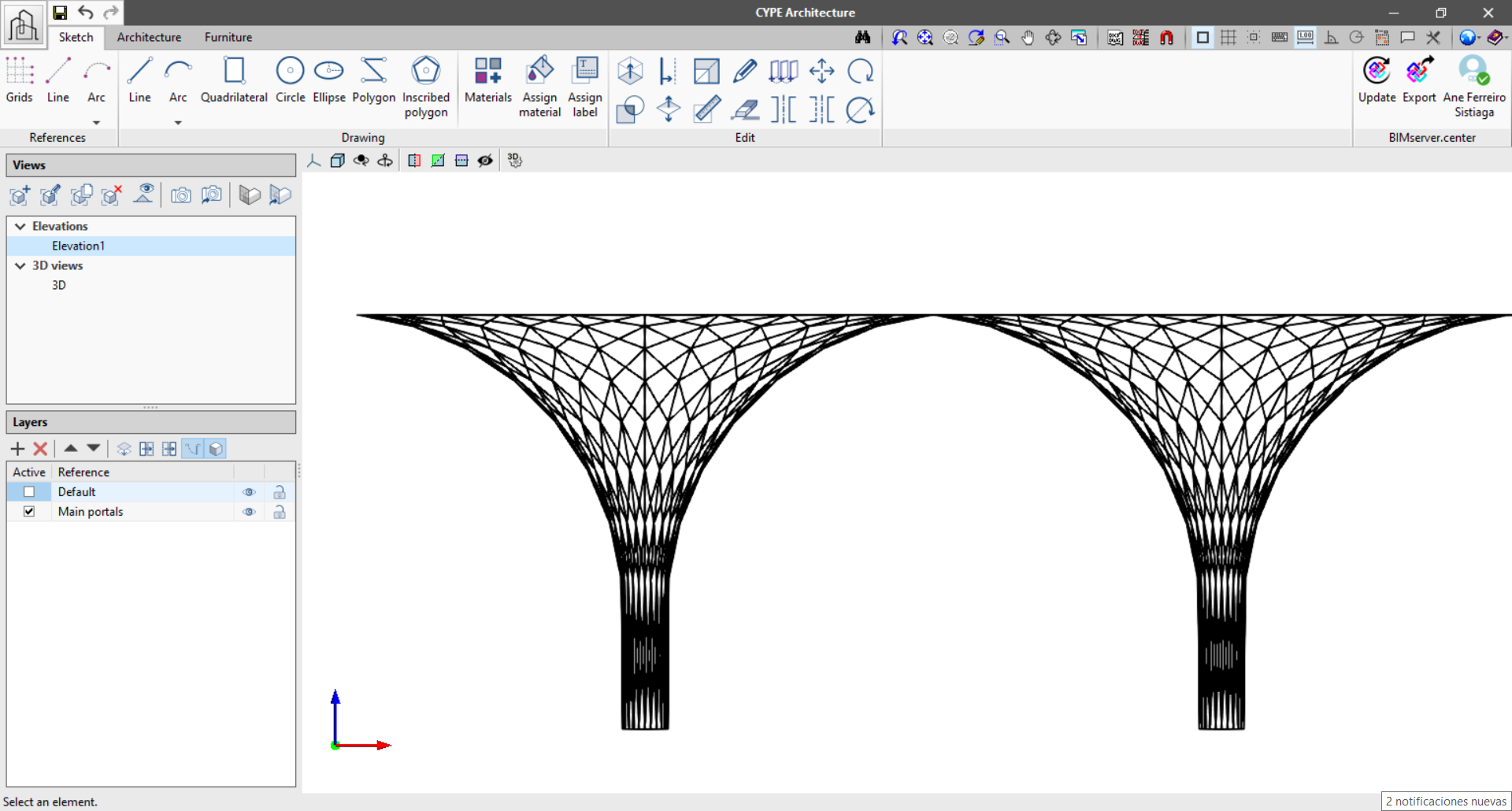
Program tools
Sketch
From this tab, users can develop the conceptual design of their project from scratch by using traditional modelling tools.
- References
With this group of tools users can draw references on which to support their models and diagrams. For example, users can activate and design a grid on which to draw a building using modular units. The references are not model elements and only serve as an aid for the 3D drawing.- Grid: Draw a reference grid that can be extended along the three axes, x,y and z.
- Line: Draw a reference through two points in space.
- Arc: Draw a reference arc by 3 points or by centre, start and end.
- Drawing
With this group of tools users can easily create a volume and floor plan sketches. These tools are already familiar to users who model with traditional 3D or CAD programs, thus facilitating the knowledge and use of them.- Line (ALT+L): Draw a line using two points in space.
- Arc: Draw an arc by 3 points arc or by centre, start and end.
- Quadrilateral (ALT+S): Draw a quadrilateral by three points, by diagonal or at a selected point.
- Circle: Draw a circle with a given centre and radius.
- Ellipse: Draw an ellipse with a given centre and two axes.
- Polygon: Draw a polygon freehand.
- Inscribed polygon: Draw an inscribed polygon in a circle with a given centre and radius.
- Materials: Assign colours to the surfaces.
- Labels: Assign labels to the surfaces.
- Edit
The editing tools interact with the elements generated by the Sketch tools.- Extrude: Extrude any type of material in the direction of normal to the surface.
- Divide: Intersect or divide two or more surfaces.
- Offset: Offset a surface towards the inside or outside of a set distance.
- Scale: Scale a surface or a group of surfaces using a scale factor.
- Invert: Invert the normal direction and the faces of the surface.
- Measure lengths: Measure elements of both the sketch and architectural elements.
- Edit: Edit the colour and the layer of each surface.
- Delete: Delete any surface or line.
- Copy: Copy any surface or line.
- Move: Move any surface or line.
- Symmetry: Allows the symmetry of a surface or a group of surfaces to be created.
- Rotate: Allows the elements to be rotated around a given axis.
Architecture
With this group of tools users can give an architectural entity to the sketch elements or start drawing the architectural elements directly.
- Vertical elements
- Walls: Wall by polyline, points or surface.
- Curtain walls: Curtain wall between two points and one height. Only sketches whole elements.
- Louvre: Horizontal and vertical louvre systems.
- Horizontal elements
- Floor slabs: Floor slab by points or per surface area.
- Roofs: Roof by points or per surface.
- Screed: Screed by points or per surface.
- Suspended ceiling: Suspended ceiling entered by sketching the perimeter by points and the location of the first plate.
- Roofs
- Roof tiles: Roof tiles entered by sketching the perimeter by points and the direction of the tile.
- Slope creation: Slope creation with a given perimeter by points and the drain.
- Ridges/Valleys: Finishing the roof using ridges and valleys.
- Structures
- Columns: Introduce columns providing their length, height and width.
- Beams: Introduce beams providing their length, height and width.
- Openings
- Door: Opens the panel to edit and introduce doors.
- Window: Opens the panel to edit and introduce windows.
- Opening: Window and door openings and openings in slabs.
- Skylight: Opens the panel to edit and introduce skylights.
- Connections
- Stairs: Allows a span of stairs to be entered individually, by points or a block of stairs.
- Landing: Enter a landing by width and length.
- Ramps: Allows a span of an individual ramp to be entered by points or by a block of stairs.
- Curved ramp: Sketch a circular ramp either individually or by points.
- Railing: Draw railing using two points.
- Swimming pool
- Swimming pool: Draw a swimming pool by using two points.
- Rectangular pool: Draw a swimming pool inputting the width and length.
- Circular pool: Draw a swimming pool inputting the radius.
- Edit
The tools in this section allow the user to edit the wall and slab solids, so that the solids can be lengthened or cut for greater accuracy in the drawing.
Furniture
The furniture tab allows users to enter furniture where the layout of the building is clear. This furniture is also able to interact with other programs in the BIMserver.center Open BIM workflow.
- Furniture
- Bed: 5 items
- Table: 44 items
- Chair: 11 items
- Counter: Two points, width and height
- Worktop: Two points, width and height
- Sofa: 12 items
- Stool: 6 items
- Microwave: 1 item
- Shelf: Two points, width and height
- Wardrobe: Two points, width and height
- Storage: 5 items
- Cooker: 4 items
- Extractor fan: 1 item
- TV: 4 items
- Computer: 2 items
- Refrigerator: 2 items
- Bathroom appliances
- Basin: 12 items
- Bath: 12 items
- Shower: 12 items
- Toilet: 4 items
- Bidet: 1 item
- Sink: 4 items
- Washing machine: 1 item
- Dishwasher: 1 item
