1.) 3Muri Module IFC – BIM (BIM2CAD) Introduction
3Muri Module IFC – BIM (BIM2CAD) enables 3Muri to be interoperable with BIM technology through IFC files (Industry Foundation Classes format), whose
specifications are based on a neutral format of data, designed to describe, exchange and share project informations.
2.) Export
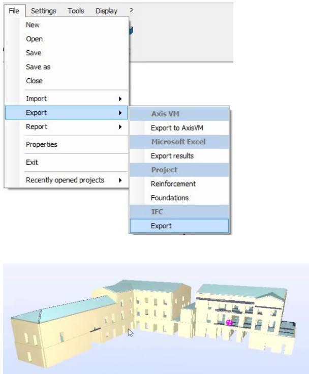
Once you have created the model, the command “IFC export” in the File menu allows you to create the IFC file. This file includes the structural objects defined by the IFC standard in order to be visible with a reader or BIM2CAD.
3.) Import
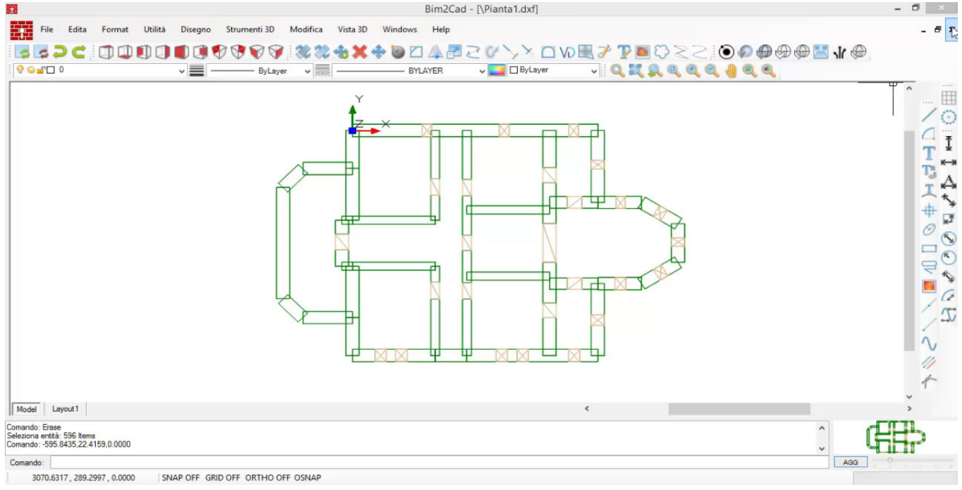
The import of IFC models is realized through the software BIM2CAD, included with the module, which allows you to read IFC files and automatically export horizontal sections in DXF format, which can be used as plants in 3Muri.
4.) BIM2CAD
Introduction
The software BIM2CAD is a CAD system compatible and interoperable with other products. It allows the exchange of information by several graphics formats: IFC, DGN (Bentley), DXF, SKP (SketchUp File), EMF, WMF, BMP, GIF, JPG/JPEG, TIF, DWG.
BIM2CAD has specific functions for the management of the IFC files.
IFC is the international standard for openBIM and registered with the International Standardization Organization ISO such as ISO16739.
IFC technology development and specifications are managed by buildingSMART International, bSI, with the following website: www.buildingsmart-tech.org.
For further information on the ICF technology see: https://en.wikipedia.org/wiki/Industry_Foundation_Classes
http://www.ifcwiki.org/index.php/Main_Page
BIM2CAD has the following functions: opening of an IFC file with 3D view, management of the filter of the displayed elements, creation of horizontal and vertical sections.
4.1) IFC Import
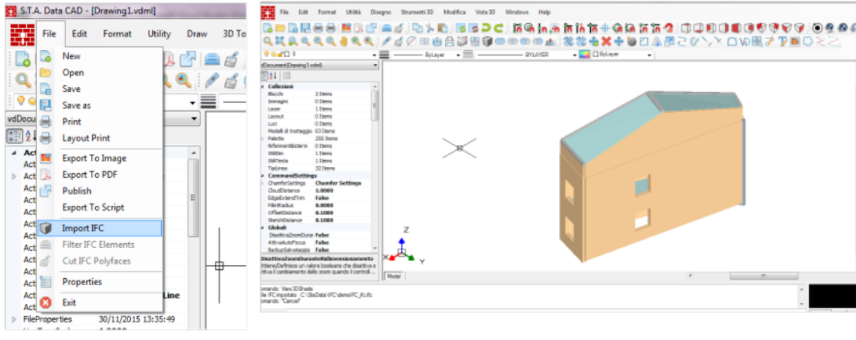
Clicking on the submenu item Import IFC on the File menu you can import a *.ifc extension file.
The file is read and displayed in the 3D view CAD area.
Note: menu items Filter IFC Elements and Create Sections are disabled until a user defined IFC file is
loaded and displayed.
4.2) Filter IFC Elements
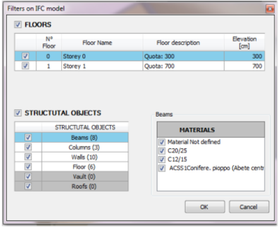
The Filter Elements function allows the user to filter the IFC model elements, according to specific
and well-defined criteria (see the image).
The first window shows all the active plans and all the active structural objects. Each structural element is followed by a number that indicates the quantity of the same type of elements in the model. If structural objects are missing, they appear disabled.
The user can add or remove the check on the titles (FLOORS and STRUCTURAL OBJECTS). If you add the check, you add every check inside. If you remove the check, you remove every check inside. The user can disable or enable the floors. In this case, the number of the structural objects will be automatically updated.
By clicking on the structural items grid the list of the materials used for the selected object type is automatically filled. Each material has a check mark for the display management (if the material is checked the filter considers the structural object associated to the displayed material otherwise it becomes invisible). The objects whose construction material is not defined are classified as Not defined material.
In the attached example image, the structural object Beams (consisting of 8 beams) is made of the following construction materials: C20/25, C12/15, ACSS1 Conifer and Not defined material.
When the user presses the OK button, the graphic area is redrawn according to the filter window user’s choices. If the user returns to the filter window, finds the checks and selections as previously defined and can change them as he desire.
4.3) Create Sections
Using this command you can create sections of the model and then save them as DXF files
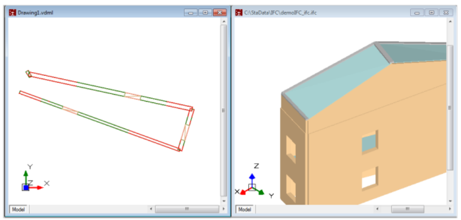
The created section is displayed in a new CAD area attached to the 3D model. If the auto saves on DXF file command is selected, the program displays a message saying that the file is created and displays the section. If the auto saves on DXF file command is not selected the section name assumes a default value (drawing1.vdml). In this case the section can be saved using the menu command File > Save As. You can create infinite sections.
It is possible to create horizontal and vertical sections.
4.4) Horizontal Section
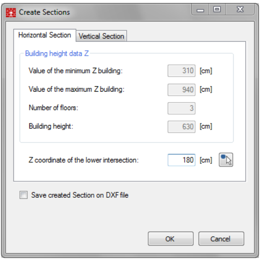
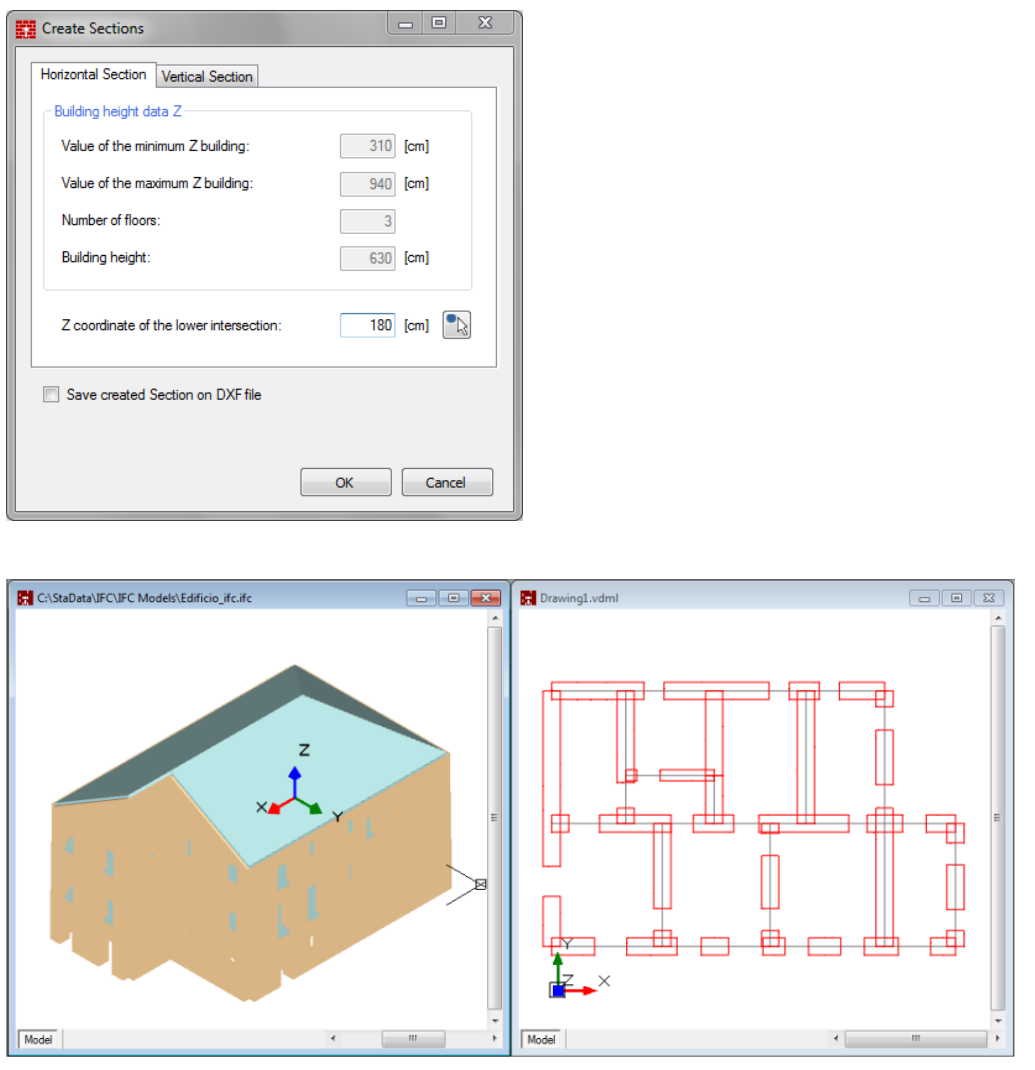
The horizontal section creation window show the height of the building data divided by:
– lowest Z of the building
– highest Z of the building
– number of floors
– building height
All dimensions are in centimeters.
The user has to insert the Z coordinate of the intersection. The user can insert it manually or by clicking on the desired point on the model. This function is
activated by clicking on the buttons on the right of the Z Intersection fields.
Check for automatic saving of the created section on the DXF file (optional). If this parameter is selected, the user must enter the name of the DXF file that will be created
4.5) Vertical Section
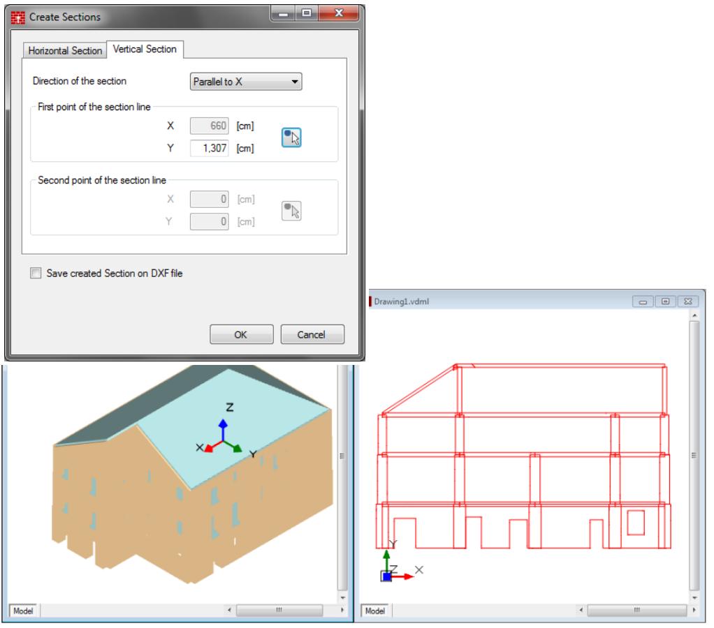
The user can select different directions to section the model.
The position of the section can be entered manually by the user or by clicking on the desired point on
the model. If the direction of the section is not parallel to X or Y, the user has to select two points.
Read more about 3Muri modules!
There are several 3muri modules that can be included in packages or ordered separately to improve your workflow. Read about 3Muri modules.
Feel free to contact us for additional information.
